Been a long time since the last update right? Unfortunately, winter doesn't exactly do wonders to finger dexterity and a simple matter of "life" has pre-occupied me for the last couple of months. Now that the weather is warming up here in Southern Ontario, however, I can get back to the CT70. In a week or so I'll be sure to bring bountiful loads of updates once I crack that engine apart.
In the meantime, I've been working on my daily commuter bike, a Honda CBR125R, which really isn't in dire need of modifications, but it looked sad and pitiful sitting there all stock =D
A couple of days ago I received a pair of frame sliders for my CBR125R in the mail. I read through the instructions (remove lower fairing, remove front engine hanger plate bolt, bolt on offset plate, then bolt on frame slider onto offset plate), but it needed the factory torque specs for the engine hangar screw plate, which I did not
have. Of course, this is where a website like CBR125r.ca comes in handy, and I logged on requesting for info.
A guy who had the factory service manual gave me the torque spec at 44 lb. ft of torque for the bolt, and I tried to go outside to install it.
First thing went wrong: The guy who sent me the frame sliders gave me M10 X 30 bolts instead of the required M8 X 30 bolts.
No problem though... the next day I went over to Crappy tire and got myself two of them, as well as two washers.
But here is where disaster struck: I was torquing the first bolt with the offset plate when the frickin bolt snapped on me! I looked at it in disbelief.
"Aw... s*$%."
Turns out that the factory service manual was vague and the guy gave me the wrong torque specs:
He wrote back after I reported my broken bolt, and I quote:
Oh crap! I'm really sorry... I think I led you down the garden path. Here is the exact section from the FSM. After this post don't listen to anything I type on this forum
Place the engine in the frame, then loosely install all
the bolts, nuts and front engine hanger plates.
Tighten the upper and lower engine hanger nuts to
the specified torque.
TORQUE:
Upper engine hanger nut:
60 N·m (6.1 kgf·m, 44 lbf·ft)
Lower engine hanger nut:
60 N·m (6.1 kgf·m, 44 lbf·ft)
Tighten the front engine hanger plates bolts
securely.
Tighten the front engine hanger nuts to the specified
torque.
TORQUE: 60 N·m (6.1 kgf·m, 44 lbf·ft)
It looks like Honda didn't feel fit to actually list the torque of the hanger plate bolts, if I'm reading that correctly.
According the FSM in the table for the Standard Torque Values lists as follows:
FASTENER TYPE N·m (kgf·m, lbf·ft)
8 mm bolt and nut 22 (2.2, 16)
10 mm bolt and nut 34 (3.5, 25)
I think I misinformed you to over-tighten that bolt by way too much... I apologize for the trouble I've caused.
Not his fault... what the heck is with this manual? Why would they be so vague on such an important bit of information as proper torque specs!?
In any case, what's done is done, so the only thing that I could do, is extract the screw...
The process of extracting a broken screw or bolt is what is known as an "adventure". This is especially true if your bolt was old and rusted... which fortunately, didn't apply to my case. However, it is a headache and if you're not careful with what you're doing, you could make things infinitely worse.
To begin with, you need the following tools: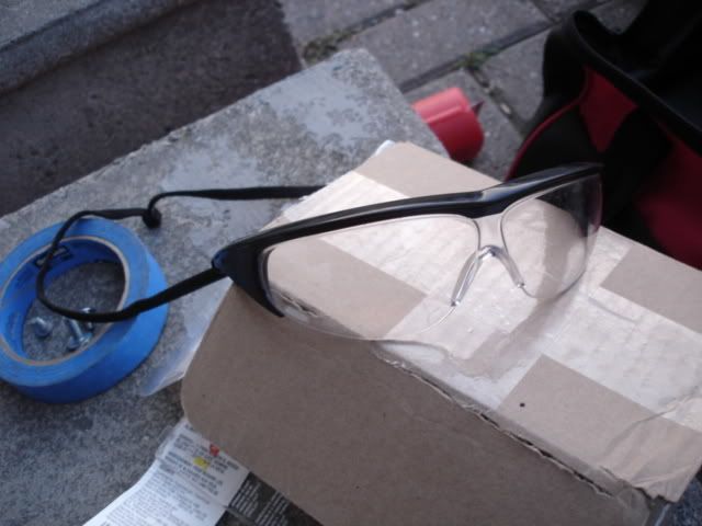
First and foremost, safety glasses (of course). You're going to be dealing with flying bits of metal... and if you mess up, possibly a high speed drill bit. A pair of cheap safety glasses is good insurance.
A screw extraction set. These can be found in most hardware stores nowadays... in fact, I picked up this Black and Decker set in Wal-Mart, for a relatively low price of $10 + tax. If you're going to be a weekend mechanic, or working on a restoration project, you WILL need these sooner or later, and they make a great addition to anyone's toolbox
An assortment of drill bits. When you buy a set of extractors, it'll usually come with a set of instructions telling you which size drill bit to use with each extractor. For example, I have a broken M8 bolt, which uses a size three extractor. This extractor bolt requires a drill bit of 5/64" diameter (yes, I love mixing metric and imperial measurements). However, I recommend you not only use the recommended drill bit size, but also include a number of smaller drill bits, and I'll explain why later.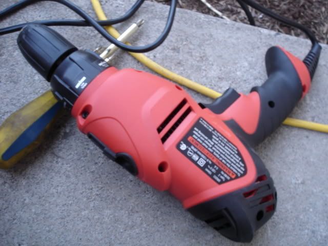
You'll need a drill. Duh...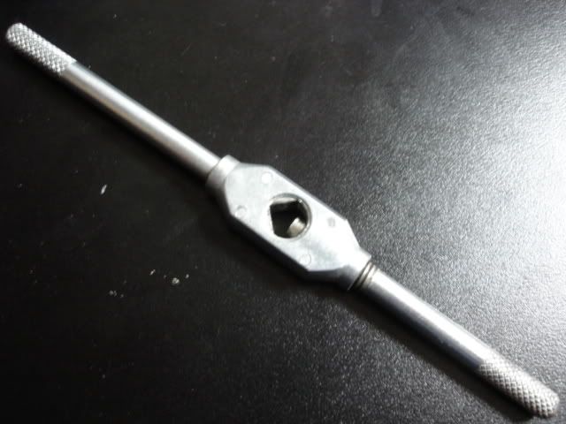
A T-bar. This piece attaches to the top of the bolt extractor. If you do not have this, an alternative is a pair of clamp pliers... but I would recommend this because it is an easier tool to use.
So now that you have all these tools, what are they all used for?
The most important one on this list (other than safety glasses!) is the extractor, obviously. The way an extractor works and the extraction process is actually quite simple and ingenious:
1. A hole is drilled in the broken bolt
2. Using a hammer, the extractor is tapped into the hole
3. Attach a t-bar onto the extractor, and... well, extract.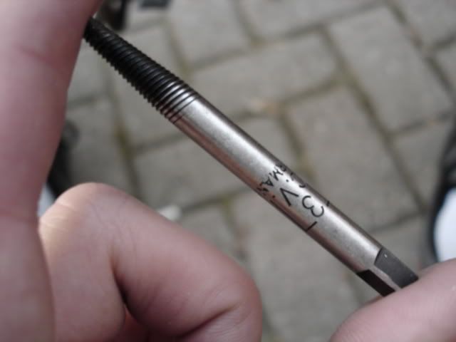
As you can see on this extractor, one end is threaded and is shaped like a cone... more importantly, those threads are running counterclockwise. What happens is that when you tap it into the hole, you attach a t-bar to it and start turning the bar counter-clockwise. The extractor will start screwing itself deeper into the broken bolt. Ideally, as it does this, the bolt will start turning counterclockwise, unscrewing itself and eventually extracting completely.
There are nuances to each step, of course.
1) To begin with, it's not exactly easy to simply start drilling a hole into a bolt. The weakest of bolts are made of medium carbon steel, which itself is already pretty solid material (these bolts will have a marking on the head of "8.8"). If you're really unlucky, you'll encounter such bolts markings as "10.9" etc., indicating heat treated alloy steel, which are 1.5 times stronger than regular medium carbon steel... (even more with higher numbers). If you were to simply attempt to take the recommended drill bit size that was listed for your particular extractor (in my case, a size 5/64 drill bit) and start drilling, you'll be at it for hours without making much progress.
Instead, start by drilling with the smallest available drill bit you have, in my case a 1/16th size bit. This does two things: a smaller drill bit will have an easier time drilling through steel; and secondly, it's easier to drill an accurate hole right in the center of the bolt with a smaller bit. This is crucial, especially if it's a hard to extract bolt (rusted in, for example), because if it's off center it'll make it even harder to extract (when you start turning the extractor you'll introduce all kinds of additional torsional forces). You can use specially made bits that are made for accurate drilling, called pilot drill bits... once again, I bought mine from Wal-Mart. Once you have your pilot hole drilled, drill again using increasingly larger sized drill bits until you reach your target size.
A few pointers: Take your time. Not only do you need to take your time in order to ensure an accurate hole, but remember to drill at moderately low revs and to hold your drill steady... or else you might snap the drill bit off. If you do this, you'll end up with a bigger problem than you started out with. Another important thing to note is to not drill through to the other side of the bolt. If you've got a drill stop, use it! The last thing you want to do is damage a engine crankcase or whatever else you weren't supposed to drill through!
And finally (and this applies only in the most desperate of cases), sometimes you'll find that the bolt is seemingly made of kryptonite and impossible to drill through. What you can try to do is to anneal it... that is, heat it up and let it cool back to room temperature. To do this, take a propane torch and start heating up the bolt in question, until it turns red hot. Use a directional flame to keep the area surrounding the bolt as cool as possible! Then, go and do something else while everything cools, and come back when your piece returns to room temperature, and try drilling again.
What you've done is changed the grain structure of the bolt. Chances are that if it's hard to cut through, it was initially put through a quench and tempering sequence that gave it a lot of strength by changing its grain structure. By annealing it, you've returned the steel back to its "original", weaker grain structure. At the same time, if the bolt was rusted in, you've likely freed up the threads a bit from the iron oxide that has built up over the years.
The reason I consider this a desperate, last resort type tactic is because you risk changing the metal grain structure of the piece you're working on as well. You have to make every attempt possible at keeping the surrounding area cool. That means to use a really small, concentrated bright white flame on the bolt in question, and hopefully not heating it up long enough that the surrounding metal turns red.
Here is how I drilled the hole in the bolt. If you'll notice, it's not completely on center, and this was because the bolt was broken off at a slight angle. Take your time with your initial pilot drill... it will ultimately determine if you're successful or not
2) Taking a hammer and the extractor, gently tap the extractor into the hole. The important thing to note here is to tap it in just so the threads of the extractor can "bite" into the bolt. Don't beat the snot out of the extractor- it is made of brittle carbide, so it is easy to break it off in the hole. If you break it into the hole, uh oh...
If you tapped it in right, the extractor should sit in the bolt cozily.
3) Attach the T-bar handle to the extractor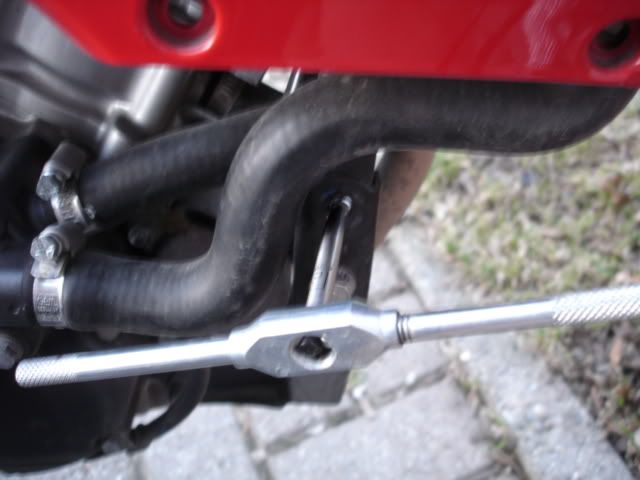
4) Start twisting the handle counterclockwise, while applying downward pressure. Make sure that the extractor has sufficient "bite" into the bolt. If it starts slipping out, then hammer it in more deeply. If that still doesn't work, drill a slightly larger hole and try again.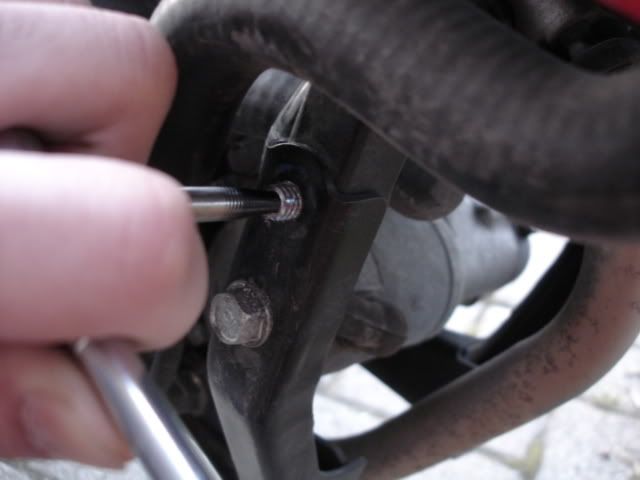
No tricks here... if your hole is on center, all you have to do is turn the handle slowly.
5) If all goes well... success!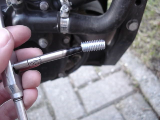

There's the little bugger. Take that and put it in your toolbox. You'll eventually have a collection of them. Each one will likely have a story attached to it, so keep them for the memories... and to warn your younger apprentices!
Sunday, April 20, 2008
Thursday, January 17, 2008
Rebuilding the Carburetor
The way an engine works is rather simple. The premise for most modern day engines is this: "Suck, Squeeze, Bang, Blow". Dirty eh?
In simple terms, what happens in the engine is this: Air is sucked in through the intake, where it is then mixed with fuel. The air/fuel mixture needs to be carefully controlled in order to ensure the cleanest and best burn possible, in order to reduce emissions and to extract that maximum amount of power possible from the engine. It is then compressed, or squeezed, reducing its total volume. The fuel mixture is then ignited (bang), which causes a mini explosion to occur, rapidly expanding the gas. This is when the best (and most important) part of the cycle happens, obviously, because this is how engines generate their power, by capturing this explosion of energy. And finally, all the waste gasses need to be expelled or blown out the exhaust.
In essence, an engine is a glorified air pump.
This particular kind of engine described is called a 4-stroke engine, and nearly all engines in use today have this type. There is also a kind of engine called a 2-stroke engine, found in older small motorcycles, older lawnmowers, chain saws and pocket bikes. And then there are really wacky engines, such as the Wankel Rotary engine (most famously used in the Mazda RX-7), as well as Compression ignition engines (more commonly known as diesels)… but those won't be discussed.
I would recommend visiting How Stuff Works for further understanding of the basics of how 4 stroke engines, if you don't already know them, as it is very helpful to know at least the basic theory before committing yourself to any sort of engine related project (duh…). The internal combustion engine is truly a marvelous piece of technology... honestly, if someone asked you to be the person who invented it, would you have thought of such an idea as the internal combustion engine?
On our 1977 Honda CT70, the first thing that needs to be attended to is the engine. Once this step is done, the rest of the bike is a cakewalk in comparison (at least until we get to the electricals). The first thing on the engine that we’ll take a look at is the carburetor. So what is this?
The Basics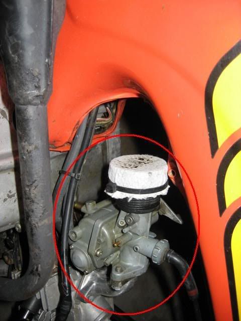
The Carburetor
In high school chemistry, you might have run across a term, "stoichiometry", those silly looking equations that determine the best ratio for a chemical reaction to occur. Ideally, in regular gasoline engines, that ratio is an air: fuel ratio of 14.7:1. Unfortunately, due to design constraints and real world losses, this kind of ratio is never achieved. Nevertheless, a "proper" air/fuel ratio is still required in order to extract as much performance from the engine as possible.
So, how is this air/fuel ratio achieved in the engine? Nowadays, this is usually controlled via computer, through Electronic Fuel Injection. In this kind of system, as air enters through the engine's air intake, the computer (or ECU) measures the amount of air flowing in. Using a series of logarithms measuring things such as air temperature, air speed, engine conditions, etc.; the ECU sends a signal to fuel injectors, which spray out a fine metered mist of gasoline into the incoming air stream. As the air stream continues into the engine, it mixes before it hits the cylinder, where the three other cycles take place. If you step on the gas, what actually happens is that the engine lets more air into the intake, and then the amount of fuel injected is increased as well. This huge amount of air and fuel causes the engine to speed up, and by slowing down the flow the engine runs slower.
However, in the bad old days, there were obviously no computers. On older bikes (and in fact, some newer bikes, such as the 2008 Kawasaki 250R), air/fuel ratios were controlled by something called a Carburetor. Click here and here for more info about the carburetor, but in essence, it serves the same purpose as electronic fuel injection:
Air comes in through the engine intake. The carburetor is basically a pipe (with attached “bits” on the outside) that connects to the air intake. As the air passes through the carburetor, the passageway narrows and the air flow accelerates (this narrowing is called a venturi). From grade-school physics, many of you should know about the Bernoulli Principle: that is, air that is moving very fast across a surface would "suck" that surface upwards (this is how airplane wings work). A similar thing happens in the carburetor. The venturi accelerates the air. Along the walls of the venturi, there are little "jets”, which look something like the tip of your mechanical pencil. 
A variety of different jets. Like a mechanical pencil tip, one end is threaded, and the centre is hollow.
The tips of these jets are exposed to the airstream flowing past in the carburetor, while fuel enters the jet through the threaded end and travels up the hollow tube of the jet. As air rushes past the venturi and continues into the engine, fuel is sucked along and mixed in with it. The amount of fuel that flows out of these jets is determined both by how large the jets are (the larger the jets the more fuel flows in), and by controlling the amount of fuel that gets to the jets in the first place (controlled via the float and float valve). The air flow is also controlled by a butterfly valve, which closes and opens the passage of the carburetor. This valve is controlled by your twist throttle.
In a motorcycle carburetor, there are often several jets, and each one serves a different purpose. In the Honda CT70, there are in essence, two: a “slow” jet, and a “main” jet. The job of the slow jet is to deliver initial fuel flow to the carburetor, to get it idling. As you twist the throttle and the butterfly valve opens up, air flow increases and creates a more powerful suction force on the jets. This more powerful suction force starts to pull fuel from the main jet as well. With proper tuning, as the amount of air flowing into the carb increases, the fuel increases to keep the air/fuel mixture at an ideal rate. As an aside, yes, EFI does this job much better, because it is able to read and adjust the air/fuel mixture much more accurately than a carburetor ever will. In addition, changes in atmospheric pressure and air temperature all affect the air/fuel mixture. Unlike a carburetor where you would need to get off your bike and fiddle with the settings manually, EFI makes things rather stupid-proof by adjusting for these conditions automatically.
So how is the amount of fuel to these different jets controlled? This is done through the float system in a carburetor. The way the float in the carburetor works is very similar to how a float in a toilet works. Fuel enters the carburetor, and eventually it sits in the float bowl, where the fuel comes in contact with the threaded end of the carb and is siphoned up into the airstream. The level of fuel that is maintained in the float bowl is extremely important. This is because the idle (or slow) jet is set at a different height inside the carburetor than the main jet: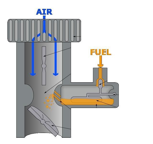
If the fuel level is set incorrectly, the jets won’t function as they’re supposed to. Too high of a level means that both jets would be on when they’re not supposed to (resulting in too much fuel in the mixture, a condition called “running rich”), or there won’t be enough fuel, if at all (“running lean”).
The level is maintained by the float. As you could see in the diagram, it’s very self explanatory. The float, as you might guess, floats on top of the fuel. When the fuel level is low, the float drops, opening up the float valve and allows fuel to come in. As the level rises, the float valve shuts off again and no more fuel enters. From the float bowl, the different jets pick up fuel depending on the suction force (which in turn is determined by air flow), and finally the air, which by now is (hopefully) mixed with the proper amount of fuel, enters the engine.
The diagram shown above is obviously a simplified example. Below microfiche showing an exploded diagram of the actual carburetor from a CT70: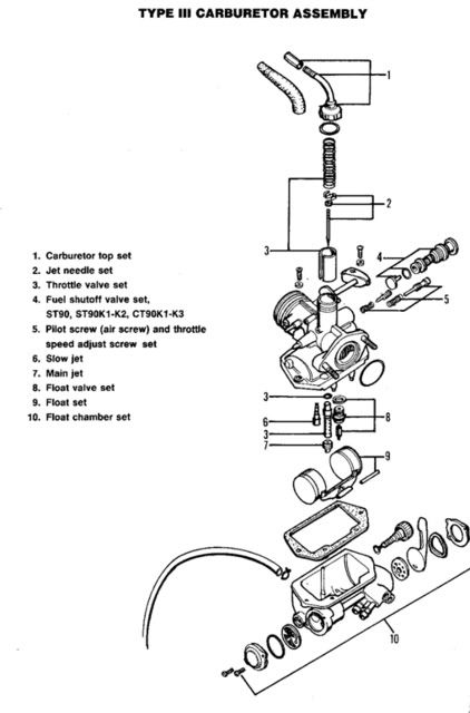
Taking it down… and Apart
One of the early problems I noticed with the CT70 is that it seems to have an unsteady idle. In addition, there was a lot of black smoke coming out of the tailpipe. Finally, when a spark plug wrench was used and the spark plug pulled off the head, it was utterly black. This meant either one of two things: The "head" or top of the engine needs to be looked at, or the carburetor needs to be rebuilt and readjusted. All these problems could be a simple problem of the carburetor needing slight adjustments (a black spark plug could mean there is too much fuel, i.e. running rich), or simple cleaning out as the jets might be getting clogged. Since the carburetor is the easiest thing to look at first, this is where we’ll start.
Disassembly of this carburetor is fairly simple. First of all, you need to do this in a place where gas cannot ignite and is well ventilated, as you'll be dealing with leaking gasoline.
The first step is to shut off the petcock valve, and then to drain the carburetor. From the exploded diagram, you could see a drain screw located at the back of the carburetor, and a drain tube that sticks out of the carburetor and is pointed to the floor. Place a clean metal container underneath that drain tube, and then open up the drain screw. This empties the fuel that is sitting in the float bowl. If you’ve used a clean metal container you could reuse the gasoline later. The alternative, slightly dangerous (and otherwise messy), is to just drain the fuel onto the floor of your beloved garage.
The next step is to remove the intake filter in front of the carb. Um… in my case that was rather simple, seeing as someone replaced the intake on my carb with literally, a piece of swiffer clothe. In a normal CT70, this step would involve unscrewing the intake and sliding it out.
Next is the throttle cable. At the top of the carburetor, you’ll see a cable attached to what looks like a chimney. Simply unscrew the top, and then carefully take out the spring, guide and needle valve.
[picture]
Press the spring inwards, and then remove the cable from the assembly. This is what controls how the butterfly valve opens, so it’s important not to lose it!
The service manual tells you to remove the fuel lines at this point. But when I tried that, it was extremely difficult to do unless you have the carb off the bike first. So what I would recommend, to make life easier for yourself, is to take the carb off the bike first, and then remove those lines. The carburetor is connected to the engine through an intake manifold… literally, a piece of curved tubing between the carburetor and the actual engine. Simply take out your socket ratchet (or wrench), and undo the two bolts that connect the carb to the manifold. Carefully pull the carb away, and stuff a clean shop cloth (or plastic bag, whatever is handy) into the manifold to prevent garbage from going in. Next step is removing the actual fuel lines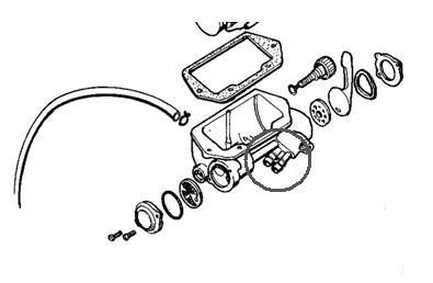
From the diagram, there are two fuel lines in total that run from the gas tank to the petcock. Why two? Since many carbureted motorcycles did not have a fuel level indicator, the simple solution is to have two settings for the fuel tank: Main and Reserve, and there is one fuel line for each. Inside the tank, the reserve line is plugged into the very bottom of the bike, while the Main fuel line is connected to a hollow tube inside the fuel tank. This tube is set at a slightly higher than the reserve. The idea is that as the fuel level in the tank drops, it will eventually go below that of the tube connected to the Main fuel line. The rider would soon realize he is nearly out of gas, as the bike starts sputtering. The rider then flips the petcock onto the “reserve” setting, which now allows fuel from the Reserve fuel line to flow into the carb, allowing the rider to ride (hopefully) to a gas station in time.
To disconnect the fuel lines, take your trusty metal container, and put it underneath the carb (away from the engine, as you’ll soon be experiencing a “slight fuel leak”). Have a pair of sharpened pencils ready, or golf tees. Tug gently on a fuel line (or use a broad flat-tipped screwdriver… be careful not to damage the lines), and as it loosens, prepare to plug the end quickly with the pencil/golf tee as it comes off the carb (once again, I emphasize that you don’t do this near sources of ignition). Then, using a piece of masking tape, or a permanent marker, flag the fuel line on where it was connected to on the petcock. The last thing you want is to run out of fuel before realizing you switched your reserve and main fuel lines! Disconnect the other fuel line in the same way.
At this point, inspect your fuel lines. If they are cracking, or otherwise damaged in any way, it would be best to replace them. It’s a simple manner of draining the rest of the fuel from the tank in that scenario, and then plugging new lines in.
Now you should be left with a (rather dirty) carburetor in your hands… a real piece of history! The next step is to clean it up and rebuild it.
Ode-skoo yo
Taking the carburetor apart is fairly straightforward. The Clymer's manual that I used didn't give a step by step set of instructions for actually disassembling it, but all you need to do is follow the microfiche, and dig in with a pair of screwdrivers (philips and flathead).
Like a box of chocolates, if your carb hasn't been touched for the last 10 years without a rebuild, you never know what you're going to get. I've seen pictures of carbs that have interior rust in them, some that have lots of gummed up residue from gasoline sitting inside and going bad (gasoline degrades into what seems like a sort of varnish when left to sit for a period of time... when it becomes like this it is also very corrosive, eating away metal like you wouldn't believe... this is why you need fuel stabilizer when you store your motorcycle or power equipment away for long periods of time), and some that just are unusable. Even if it looks fine, check the condition of the float bowl: if you see lots of pitting, or there seems to be "coral-reef like" shadow on the bowl, then it's gone.
Fortunately, replacement carburetors are very inexpensive and easy to find, on websites like eBay or the billion or so trailbike websites. You could typically expect to pay less than $50 for a new one... however, for period correct ones expect to pay a far greater premium as they are, obviously, discontinued. If you've got a carb in good condition and you want to keep things "authentic", try restoring it first, before anything else, as spending $200 or so on a NOS (new old stock) carburetor isn't cool.
Luckily, besides a bit of griminess and wear from 30 years of use, my carburetor is more or less alright. If you're going to rebuild the carburetor, it is recommended that you get a full rebuild kit, which could be found easily at places like eBay for a low price as well. What you should get with a rebuild kit are new gaskets, jets, needle valve set, and springs. Very simply, just replace the old parts in your carb with the parts in the rebuild kit.
Before that, however, you should pick up a container of carburetor cleaner. These can be found in motorcycle shops, hardware stores and places like Crappy Tire (Canadian Tire). They usually come in a resealable container, and can be stored and used for several cleanings. Take the carburetor completely apart, set aside the old parts that are replaceable with parts from the rebuild kit, set aside all non-metal components (they will melt in the carb cleaner), and then dunk the rest of the parts in the carburetor cleaner itself. What I did was let it soak overnight, then the next day I took an old toothbrush and went at 'er, scrubbing away all remaining traces of gunk.
Reassembly the carburetor, and put everything back on the bike. At this point, you're almost ready to test the engine out again- but first, you have to readjust the pilot screw and idle screw. The Clymer's manual recommends that you actually attach a portable tachometer to the motorcycle and then set it to the correct RPM, in this case 1300 +/- 100 rpm. Unfortunately, I didn't have a tach, so what I did instead was use my ear and wing it, putting the engine idle to where I thought the idle should be. I don't recommend you doing this though =P
At this point, you're done.
Problems
Or, at least, in a perfect world everything would be done with no problems at all. Unfortunately, that didn't happen in my case.
After putting in the carburetor and trying to fire the CT70 up... nothing happened. I tried again, furiously hitting the Kickstarter a few times. Still nothing. Troubleshooting time =/
First thing I did was check to see if fuel was getting into the carb. So I turned the drain screw to see if fuel was flowing into the carb... nothing was coming out, so the fuel is clearly held up somewhere before it entered the float bowl. I unscrewed the petcock a bit, and the fuel that leaked out slightly told me that all was well there. Then I unscrewed the fuel filter portion- same thing. A little bit of head scratching later, I realized that what happened was the float level wasn't set properly- the float was incorrectly adjusted to the point where it didn't even allow fuel to enter the bowl through the float valve. A bit of twisting around, reassemble the carb, and I smiled as fuel came out of the drain tube when I loosened the drain screw.
I smiled again when I hit the kickstarter and the engine came to life on the first kick... and then my smile promptly disappeared. Coming out of the bike was a huuugggge cloud of black smoke. I readjusted the carb a couple of times to see if that would solve the problem, but it didn't do anything. On top of that, the idle was unsteady. I tried adjusting the pilot screw and air screw a couple of times, but the bike randomly revved by itself and then nearly stalled at intervals.
It's clear at this point that the problem is much more serious- something might be wrong with the cylinder head, or the actual cylinder and piston rings are screwed up.
The next step then, is to investigate these areas to see if they're the cause of the problem. To verify that it isn't indeed the carburetor's fault, a compression test would need to be done on the cylinder. Basically, this test involves removing the spark plug, attaching a meter to the spark plug hole (the meter looks a lot like those blood pressure monitors you see at the doctor's), and then compressing the engine a few times by simply kicking on the kickstarter a few times to turn it over. The reading on the compression test should show about 150 psi... if it doesn't, then either the piston rings aren't forming a tight seal between the piston and cylinder wall, or the cylinder head's valves are messed up.
I actually don't have a compression tester on me, but the old mechanic's trick is to cover the hole with your thumb and then seeing if the force is strong... it should give a general idea of the state of things. I'll perform this test soon, and pop the cylinder head off to see what's going on.
Sunday, January 13, 2008
Welcome!
This is a new blog I set up to document all the projects and such that I've been working on... everything from computers (which I despise) to cars (which I love).
Introduction To The Game
So, to start things off, as many of you who were re-directed from my main blog know, I have been looking everywhere for a project motorcycle of some sort, as I was bored and wanted to try something knew. I'm no stranger to machines and engines, as I've worked both as a die-cast technician during my first work term at Exco Engineering, and on the Formula SAE team at the University of Waterloo, putting things together.
Now, allow me to introduce my new project, a 1977 Honda CT70: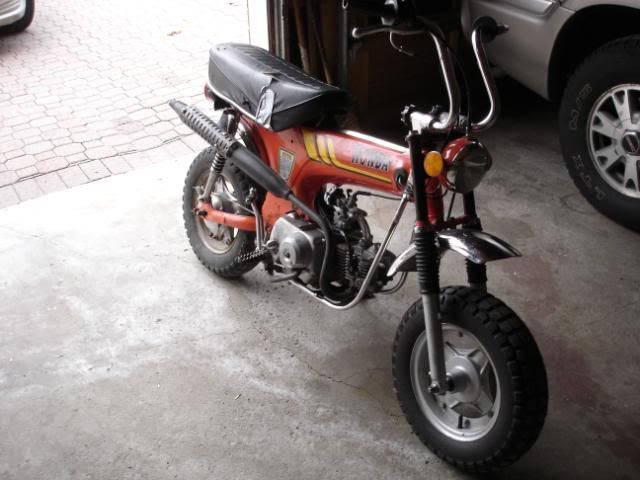
I've actually never even heard or batted an eye at the Honda CT70 until I saw the epic Honda: Impossible Dream commercial
I noticed the Passport, and then I saw the freaking Z50 and that immediately caught my attention. For sure I never knew Honda had made a minibike. I don't know why but I started doing some research, and read about Honda's 50-110cc SOHC single cylinder air cooled engines.... this is one of the most important engines that Honda has ever made (EVER, both in cars and powersports) because this very engine is what propelled them into one of the largest manufacturers of powersports and automobiles in the world. I looked around at a couple of these bikes, intrigued because of their simplicity, cheap-ness to own and maintain, and their historical significance.
I was originally about to purchase a Z50... but in the GTA region in Ontario, all the models I could find seem to be the late, plastic-ridden Z50R's of '92+ vintage. Then I saw a listing on Kijiji for a CT70. From all my searching, I realize that these bikes are one of the rarer ones (in Ontario, at least), and when I saw it in person, I had a huge smile on my face. It looked way better in person than it did on google imagesearch. I knew it was a bit rough, but I took it anyways because it was in running condition and because I got it for around $400... a good deal IMO because the 92+ Z50R's I saw were being offered for 800-900 bucks (!?). Not to mention it was the only one I ever saw on Kijiji.
And now, here we are.
Overview
Due to Ontario weather, the sun only comes up at 7-8 AM and goes down at 5... so all my pics are in the dark. Nonetheless I'm hoping they are enough to highlight some of the many quirks on this bike:
Here is my pride and joy... a 1977 Honda CT70. While in somewhat good condition, you can see some things immediately wrong with it:
1. The "Honda" sticker is clearly not stock, though those stripes are. Why a previous owner replaced it I'll never know. Also, the warning label is missing from this side...
2. The Headlamp ears. This has been one of the more confusing parts about this bike because it seems so stock... if a previous owner jacked it, s/he did a really good job making it look nice. I'll emphasize as we continue...
3. No signal lights. Either a previous owner removed them, or they were never present. I'll emphasize as we continue...
Coming around to the rear, the rear hub is rusted, no apparent brakelight switch (if there ever was one for this bike), the trim for the seat is bent outwards so I had to duct tape it for now to keep it from stabbing me when I kickstart the bike, and the rear tail-light is clearly not stalk (although the bracket is... according to the man who sold it to me.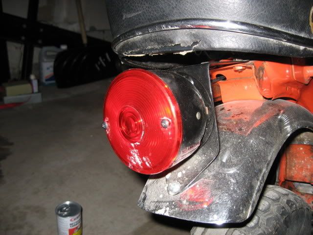
A closer look at the light. Where were the rear signal lamps supposed to connect to? And is there an attachment for the bracket for the license plate? In Ontario, I believe that most (if not all) bikes were sold as off-road only, but I would like to take a stab at making it road legal. P.S that's a can of carb cleaner =P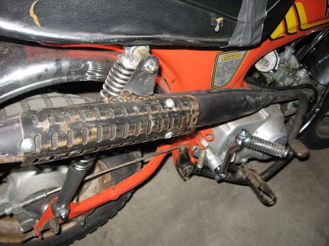
The exhaust works fine, but that's all that remains of the heat shield. It's very ghettotastic (especially the poor... weld job? Where it broke off) , so I'm likely going to replace it with a new aftermarket one for $30, from WebLLC on eBay. The seat clearly needs replacing, although the foam and seat frame is fine. I just replaced the kickstarter, as the man I bought it from tried to start it in front of me and broke it =)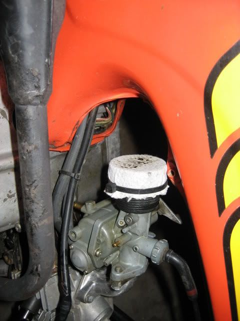
Okay, there's CLEARLY something wrong here. I don't know what happened to the intake, but it's safe to say that a piece of clothe that's been zip-tied in front of the carb ain't going to cut it. A new plastic aftermarket intake replica will be purchased from webLLC as well.
Okay, now this is my biggest piece of weirdness... this black fork ear piece is clearly not stock...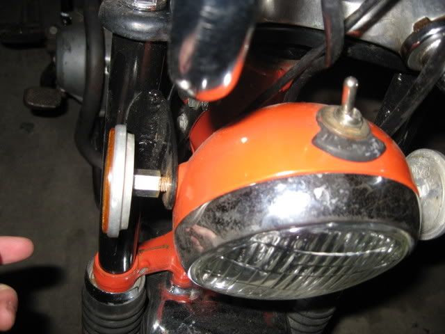
Why is it so weird? The reflectors are screwed INTO the headlamp (which is unusual too), to keep it into place. From what I see, the lamp is supposed to be held to the ears with bolts. The reflectors are supposed to be mounted on the bottom of the fork ears, and there should be another hole drilled in for signal lights.
Most importantly, WHY IS THERE A SWITCH ON TOP OF THE LAMP? It's an on/off switch, except turning it off turns off both the headlamp AND taillamp :confused: That's not an original feature is it?
It's also hard to see from this angle but there's no speedo either...
The back of the reflector holding the headlamp onto the ears. Are these OEM?
This is possibly the biggest problem of the bike right now... as I open up the seat, there is nary a blip of battery-ness in there. For that matter, there's nary a presence of wires anywhere (I'll explain why this is bad in another post as I get closer to the task).
When I first got the bike, it didn't start up, even after I put a new kickstart on. I got a sparkplug wrench, popped her off, and it was completely black.... I put a new one in and it started first kick (without the choke on...). After idling for a bit, I noticed that the idle was not steady, and there was the smell of unburnt gas... oh, and there was smoke coming out the back of the bike. With the fact that there was choke-less startup, snappy throttle response when you get on and ride it (great fun btw, and the shifting is smoooth), it is clear the carburetor is not properly calibrated. I bought a carburetor rebuild kit as well as a manual (on eBay... where else?), and am going to rebuild it sometime tomorrow.
Oh, and this is very important: Whenever you're starting a project, or if you have a car/motorcycle/whatever, the first thing you must do is get a service manual for it. This is your most valuable tool. As they say, knowledge is power, and a service manual that basically tells you how to take your product apart and put it back together again is one of the best resource you can have, other than your common sense and technical know-how.
For all of Honda's various 50-110cc models, you should get this particular one:
It covers not only the CT70, but everything from the Supercub (the motorcycle that changed the world) to Z50's, to SL65s. You could even use the portions of the manual covering "engines" for some of the classic Honda ATVs.
The previous owner claimed that the head had great compression, so I'm not entirely sure if that's partly to blame for the crazy smoke coming out the back of the exhaust pipe. However, I'm buying a compression check tool (off eBay... I'm a eBay whore in case you didn't know =P) to check that out later on. If it turns out to be the head, I'll probably just buy an entirely new head off eBay, as I found a listing (relisted every once in a while) for a CT70 head with the proper "big dome" for my CT70.... $60. If that STILL doesn't fix it, I'll get a new cylinder and piston kit, and gaskets too ($60).
Assuming that all that is fixed, I'll need to tackle the actual bike itself. I've looked at all my options, and seeing as my budget is constrained somewhat, I figure I can knock off several birds with one stone if I buy a 12V CDI stator/flywheel kit, as well as a complete wiring kit from WebLLC. For a total of $200 USD or so, this is potentially the cheapest way to bring this bike to it's original fully-functional form.
Here are some eBay links for items:
Complete Wiring Kit for Honda 50-110 OHC engines
Conversion Kit from 6V points type Stator/Flywheel combo to a 12V CDI combo
This will take care of my turn signals, horn, new headlamp + speedo ('69-70 style unfortunately, but that's fine) w/ high/low beam, a battery, refresh all the control lines, tail lamp that looks original w/ actual working brake light, brake switch, etc. Also, no more fiddling with the stupid points. It won't be original anymore, but I figure if I resell it the next owner probably wouldn't mind, compared to the condition I found it in. It'll also be fully street legal after this install. I'm also debating whether I should keep all old parts (for repair as well as giving it to the next owner... if I decide to sell it... for added "original-ness"), or sell it all on eBay. If the next owner wants, I figure s/he could turn it back into a 6V bike by changing the bulbs, battery, rectifier/regulator combo, and reinstall the old 6V flywheel/stator (I'd rather have the 12V and the brighter lights).
Once that's all done, it's just aesthetic details... does anybody know the paint code for this year? I'm not a big fan of orange, but I'm not ready (yet) for a complete repaint, but I need to touch up the exposed surface rust. I will, however, clean up the engine and wheels, and replace the seat cover and exhaust. The fenders are more or less fine, save for a few dents, and I'll be sure to replace those brake shoes and wheel bearings/seals.
My main goal with this bike is to bring it back to perfect running condition, and to turn it street legal (with turn signals, hi/low beams, horn, etc.). Whether or not I'll actually go and plate it is another thing, but it's cool to restore any vintage item back to how it was supposed to be. If I ever have to work a co-op term at a random far off place, it's a simple manner of folding the handlebars and throwing this bike into my trunk as a better (and faster) commuter than a bicycle =P
More to come....
In the meantime, I've got a lot of other stuff to do too. I've been eBay-ing for parts for my bike, and I've now got a battery tray.
I've also taken somebody else's old cylinder head for $10, as it seems that I might need to fix my own: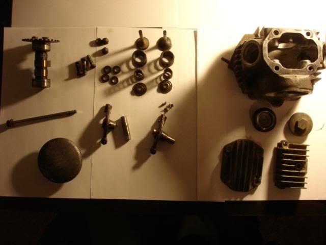
It's got everything. Starting from the left: Camshaft/timing gear, cover and bolt, various screws and nuts and washers, valves, valve springs (inner and outer), retainers, cotter pins, rocker arms/pins, the actual head, tappet covers, and engine covers. You could see with the small amounts of parts here how simple Honda's 50-110cc engines were. These very parts on my table, however, are what's used in all piston-driven engines today.
Finally, I'm also going to be doing some inexpensive upgrades to our home desktop computer (which is old and craptacular). As you'll probably soon see, it doesn't take much to bring a otherwise old machine "up to date" to play many recent games and for a significant boost in system performance. Stay tuned!